
As I await my turn in line, I have begun thinking of different mounting options or panel type designs. Anyone have any photo's of how you have added this to your system? I understand the basic system design - this will be integrated into my HERMs (kinda...) system.
-Jay
integration mounting pics?

Re: integration mounting pics?
I am working on my panel right now .. it is not ready for a picture.. I got stuck on fabricating a bus to make the routing of wires inside the panel cleaner. the unit will have 4 D2425 SSR's and two of which are mounted on a heat sink . a small fan pulls air through some knock outs across the heat sink and out the top of the unit. These two SSR's will be used for heating elements. and the other two .. one is for a pump .. maybe another pump is in my future.
Brett
Brett
Re: integration mounting pics?
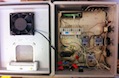
Here is mine so far.I can't seem to embed the photo so here is a link : http://picasaweb.google.com/lh/photo/Zz ... directlink
It has 4 D2425 SSR. 2 of which are mounted to an old Intel P4 heatsink. A fan at the top of the box pulls outside air across the heat sink from knockouts. I used silicone base heatsink under all SSR's
the outlet inside the box to the upper left holds the BCS transformer and the fan and blue LED indicator light transformer. After I started building it,
I figured a busbar would save tons of space and make the 110v wiring much cleaner. I took the busbar that came with the load center box and cut it in half.
I fabricated 2 isolators to keep both busbars off the panel. I used CAT 5 cabling to wire the SSR's. the outlet on the right of the box is double duplex.
I snipped the brass in between the 110v mounting screws so each outlet is an output from each SSR, independent of each other.. the covered switch at the left
outside of the box is a master switch that kills power to the entire box inlcuding the BCS. Next I am going to make another hole with rubber grommet to output the
temp probes. I used power connectors to make a plug for the SSR activation wires. A Cat 5 patch cable and Cat 5 extender. lets me remove the BCS if needed. I connect a 25 foot Cat 5 cable to this extender to program the BCS or run in manual mode. The BCS itself is mounted with heavy duty velcro, so it can be removed.
the temp probes will also be made with connectors in the box, so they can be unplugged. Next I am going to install master force on switches for each SSR. Thanks to EEC, I now know how to use a 3 way switch to do this safetly using 6v out terminal on the BCS. If anyone has any questions please feel free to ask.
Re: integration mounting pics?
Looks great! Any wiring diagrams?
I'm looking at making a "Main" unit and a "remote" unit and be able to interconnect them with a network cable. This is so the main can be over where my fridge is and the remote can be in the brewing area. I'm sure that the remote can support upto about 50f without a problem.
Anyway - I'm trying to get the wiring concept out of my head and get a diagrm up. I'll post it up once I get it down.
-Jay
Re: integration mounting pics?
actually I didnt draw a diagram for it. I was an auto mechanic for 10 years and home circuits are basically the same. I just layed the components and wired it as I went along
I need to take a better picture since the flash washed out the details. I will do that in the AM . maybe then you can see the wire paths and get a better idea of how its wired.
I suppose I could draw one up but it wont be pretty. I dont have a program for drawing circuits on my macbook. I used to have a program though.. I should try to find it or download one.
Re: integration mounting pics?
here are some better quality pictures. wish I could remember how to embed them.
http://picasaweb.google.com/lh/photo/tg ... directlink
http://picasaweb.google.com/lh/photo/TX ... directlink
then you can look at other photos in the web album . the last 3 are from this AM and are better detailed.
Brett
http://picasaweb.google.com/lh/photo/tg ... directlink
http://picasaweb.google.com/lh/photo/TX ... directlink
then you can look at other photos in the web album . the last 3 are from this AM and are better detailed.
Brett
Re: integration mounting pics?
You need to put  at either end of the URL to show an image. Like this:


Re: integration mounting pics?
Brett, do you have a part list?
Re: integration mounting pics?
not really but I can try.
4 crydon D2425 Solid state relays.
1 GE 125 amp load center box 12" by 12"
1 90 deg. conduit elbow for 1/2 inch knockout
25 feet gauge 12 romex 120v good for 20 amps
1 Metal double duplex outlet housing w/4 hole cover
1 plastic single outlet housing w/ cover
10 feet plastic sleeve black.
1 12 volt transformer for cooling fan
1 2" computer fan
1 old pentium 4 heatsink
main switch is an extension housing and cover plate (outdoor)
1 main 120v light switch
1 20 amp outlet plug brass in between the plugs is cut away , this lets you use each plug separately
2 15 am outlet plug brass in between the plugs is cut away , this lets you use each plug separately
20 amp plug end replacment grounded.
5 feet Cat5 cabling.
1 6 inch Cat5 patch cable.
1 Cat5 extension plug. (this is glued into a knock out so I can plug 25 feet cat5 cable and program the BCS.
tie downs
tie down anchors.
I had to cut the ground/neutral busbar in half and fabricate 2 isolaters on each end. drilled and tapped the ends (they are not available separate from the load center)
the plastic is some kind of shelving 90 degree piece of plastic with holes in it.
1 9 position power connector male (radio shack)
1 9 position power connector female (radio shack)
Radio shack also had a small fan for 12 bucks. I took one from an old Xbox cooler add on for an Xbox 360
the box came with a cover plate on the top. I drilled holes in this plastic cover and bolted the fan to this to blow air out.
this pulls cool air in from the bottom knockouts over the heat sink . the march pump SSR is mounted straight to the back of the box with silicone based thermal paste (Radio Shack)
various machine screws nuts washers and lock washers.
I think thats about it. the project is on hold while I look
into rewiring for 2 20 amp lines and 2 water heater elements in a small HLT. the 2 SSR's on the heatsinks would supply power for the elements. the need it.
And I have to run 2 20 amp 110 v lines from an outside breaker panel nearby.
Re: integration mounting pics?
Here is my box. The RJ45 on the top is for the BCS. The Duplex box on the left has two RJ45s that I will use not for LAN but to hook two remote boxes to this box. I want to have a box to run my fridge with 2 SSRs and a temp probe and another for my chillzilla heat exchanger.
- Attachments
-
- IMG_0185.JPG (149.47 KiB) Viewed 7959 times