Here is my Pid setup, Still working on dialing it in.
http://rabeb25.mikesdecks.com/BEER/MISC ... %20Tuning/
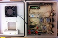
Here is my PID (work in progress)
Re: Here is my PID (work in progress)
Can you give some explanation about how you read/tune this information? I know enough about pid programming to know that I know nothing about pid programming, i cannot even claim to be much more than mildly inept, never mind dangerous.
Check out the Brew Buddy for iphone controlling your bcs-460.
Re: Here is my PID (work in progress)
Well I honestly just found out from Adam, 2 nights ago..SO I am really not the man to explain it. I am in the same boat as you Noah. I did get my overshoots fixed though.. and they were completely un-related to my pid tuning... go figure 

Re: Here is my PID (work in progress)
I have a placeholder on the wiki to start documenting and explaining the PID controls. Its blank now, but check back 
http://www.embeddedcontrolconcepts.com/ ... ementation
http://www.embeddedcontrolconcepts.com/ ... ementation
Re: Here is my PID (work in progress)
I am the same as you guys, know the concept , but little else.
I did find that my system worked very well from the beginning with almost no overshoot (1.3 deg F). I have not plotted them though - just visual observation. This was the single AHA moment for me, as the cheap PID I used to use always overshot and no matter what I did I could NOT fix it.
In 2nd 3rd and 4th batches I did not notice as much overshoot, but I did also mash in closer to accurate temps, first time out I deliberately mashed low to do a step mash to see actual step times. I am monitoring two temps during the mash, both the actual temp at the output valve of the mash tun , thus as close to real mash temp as I can get without putting the thermistor into the mash itself, and I also monitor the out put of the RIM heating chamber (1500W 110 volt) to see how much differential in temp I am seeing . Amazingly I only see about 5-6 deg max difference when heating is ON. There is 6ft of copper pipe between the two points , some of it insulated but not all, so know I get a bit of cooling in the winter from heater to mash tun.
I now have a third Thermistor , so next batch - Saturday - will monitor the actual temp of mash being pumped back into the mash tun , just for interest.
I will try and remember to plot my results this weekend.

Re: Here is my PID (work in progress)
I got the temp probe from ECC. when I ran some tests in the pasts days I had no overshoot of temps at all.
I just set the temp and selected pid. and it never went over the set point. I am so glad I dont have to mess with that.
the temp probe is inline of the outlet of the HLT in a SS "T" fitting, from there it goes straight to the pump and back to the
HLT with, 2, 2KW 120 volt elements. I can try a screen capture next time I run the system, but its all set to whatever
Adam set them to.
Brett
Re: Here is my PID (work in progress)
One thing to keep in mind with the PID settings is that the integral coefficient can be very sensitive. If you have a problem with the loop basically working correctly, but not quite giving it enough "umph" to get to the set point... you can add a small amount to the integral coeff. The integral coeff is basically looking at the sustained error over time. The longer the time where the error is negative (lets say), then larger the integral error... therefore the larger the total correction.
Its exactly what it says it is... the integral coefficient is looking at the area under the error curve. The larger that area (meaning a sustained error), the more it will contribute.
I tweaked my PID loop by only changing the integral coefficient from the default settings. The default integral value is 0.1. I am using 0.22 now, and it holds temp like a champ. 0.3 gives a little too much overshoot for me (over 153), and 0.2 is not quite enough to maintain 152 on my mash. It'll hover around 151 - 151.5.
I am using a single 3500W 240V element on 120V. Works pretty well.
Re: Here is my PID (work in progress)
WHAT?WolfPlott wrote:One thing to keep in mind with the PID settings is that the integral coefficient can be very sensitive. If you have a problem with the loop basically working correctly, but not quite giving it enough "umph" to get to the set point... you can add a small amount to the integral coeff. The integral coeff is basically looking at the sustained error over time. The longer the time where the error is negative (lets say), then larger the integral error... therefore the larger the total correction.
Its exactly what it says it is... the integral coefficient is looking at the area under the error curve. The larger that area (meaning a sustained error), the more it will contribute.
I tweaked my PID loop by only changing the integral coefficient from the default settings. The default integral value is 0.1. I am using 0.22 now, and it holds temp like a champ. 0.3 gives a little too much overshoot for me (over 153), and 0.2 is not quite enough to maintain 152 on my mash. It'll hover around 151 - 151.5.
I am using a single 3500W 240V element on 120V. Works pretty well.
Good info. I haven't a clue what an integral coefficient is, but I'm gonna play with it based on your message. Thanks.
Re: Here is my PID (work in progress)
OK, can someone explain what iState is? Its listed in the algorithm, but it is not defined.
The PID control scheme is named after its three correcting terms, whose sum constitutes the PID output, a number from 0-100%.
pid_output = pTerm + iTerm - dTerm;
where
pTerm = pGain * err;
iTerm = iGain * iState;
dTerm = dGain * (curr_temp - previous_temp);
-
JonW
- Site Admin
- Posts: 1726
- Joined: Sun Jul 18, 2010 7:51 am
- Bot?: No
- Location: Huntington Beach, CA
- Contact:
Re: Here is my PID (work in progress)
bg110 wrote:OK, can someone explain what iState is? Its listed in the algorithm, but it is not defined.The PID control scheme is named after its three correcting terms, whose sum constitutes the PID output, a number from 0-100%.
pid_output = pTerm + iTerm - dTerm;
where
pTerm = pGain * err;
iTerm = iGain * iState;
dTerm = dGain * (curr_temp - previous_temp);
Here's a reference that explains it: http://m.eet.com/media/1112634/f-wescot.pdf