My Tentative Plan

Suggestions, Problems, Availability, etc. Everything is up for discussion.
slimer
Posts: 21
Joined: Fri Jan 09, 2009 9:36 am

My Tentative Plan

Post by slimer »

Here's a tentative plan of how I'm going to set up mine when it arrives. I may have to do it in stages.

Image

Edit: Original Pic had mistakes.

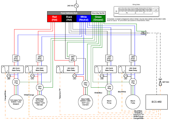
Also, This version is a little cleaner. The orange dash lines is CAT5 cable or Twisted pair and the black dashed lines are the power sources for the constant on.
Last edited by slimer on Tue Jan 13, 2009 7:42 pm, edited 1 time in total.
User avatar
ECC
Posts: 676
Joined: Fri Sep 12, 2008 12:29 pm
Bot?: No
Contact:

Re: My Tentative Plan

Post by ECC »

Very nice. What's the 240v element for? Is that for the Boil Kettle?
User avatar
ECC
Posts: 676
Joined: Fri Sep 12, 2008 12:29 pm
Bot?: No
Contact:

Re: My Tentative Plan

Post by ECC »

Got it now with the update.

Question: would it be better to run the HLT and RIMS on different legs of the 220? Since they'll likely be on at the same time, seems that they'd be more balanced that way? I'm by no means a 220v expert (I like my voltages in the single digits), so I'm asking not giving advice :)
slimer
Posts: 21
Joined: Fri Jan 09, 2009 9:36 am

Re: My Tentative Plan

Post by slimer »

I was considering going off different legs. I'm no expert either, but it would make sense to put a pump and an element on each hot.

Since I don't have my unit just yet (should get it tomorrow) I don't know exactly how to wire the SSR's, but I'll be doing some research.

Also, I have one more space for an output. Any suggestions?
slimer
Posts: 21
Joined: Fri Jan 09, 2009 9:36 am

Re: My Tentative Plan

Post by slimer »

After reading a little about the manual/Din mode, I may sub the switches for 3 toggle switches instead.
User avatar
ECC
Posts: 676
Joined: Fri Sep 12, 2008 12:29 pm
Bot?: No
Contact:

Re: My Tentative Plan

Post by ECC »

The SSR wiring is pretty easy, just wire the "+" pin of the SSR (sometimes labeled input or control) to the Out pin of the BCS, and the "-" pin to any of the BCS GND pins. The output side of the SSR can be thought of as a big switch, use it to break the hot line going to your element/pump.
User avatar
bsfixit
Posts: 170
Joined: Thu Dec 25, 2008 4:26 pm
Contact:

Re: My Tentative Plan

Post by bsfixit »

thats a cool drawing.. what program did you use to create it ? Also doesnt LED indicator lights need some kind of driver cause they cant run off 240v . or you can put them on the DC side of the SSR.
really cool though ..
slimer
Posts: 21
Joined: Fri Jan 09, 2009 9:36 am

Re: My Tentative Plan

Post by slimer »

I made it in Microsoft Visio.

I have made a few adjustments to the drawing since this morning, but my work computer caught a cold, so no go today.
np0x
Posts: 110
Joined: Wed Oct 15, 2008 7:16 am
Bot?: No
Location: Vienna, VA

Re: My Tentative Plan

Post by np0x »

Also doesnt LED indicator lights need some kind of driver cause they cant run off 240v
FWIW: you can get 110V ac powered "voltage indicators" from radio shack easily. They look like LED's but run on high voltage AC.
Check out the Brew Buddy for iphone controlling your bcs-460.
User avatar
bsfixit
Posts: 170
Joined: Thu Dec 25, 2008 4:26 pm
Contact:

Re: My Tentative Plan

Post by bsfixit »

np0x wrote:
Also doesnt LED indicator lights need some kind of driver cause they cant run off 240v
FWIW: you can get 110V ac powered "voltage indicators" from radio shack easily. They look like LED's but run on high voltage AC.
True .. they are neon based indicator lights.. not true LED. I have one for testing outlets. glows red. Speaking of LED I have some super bright blue ones I could add to my box
just for some bling bling ! ! working on installing the new double 20 amp GFCI outlet at the brew stand sometime soon, got all the parts at lowes today.
dont forget the 120v transformer for the BCS power.
Post Reply